


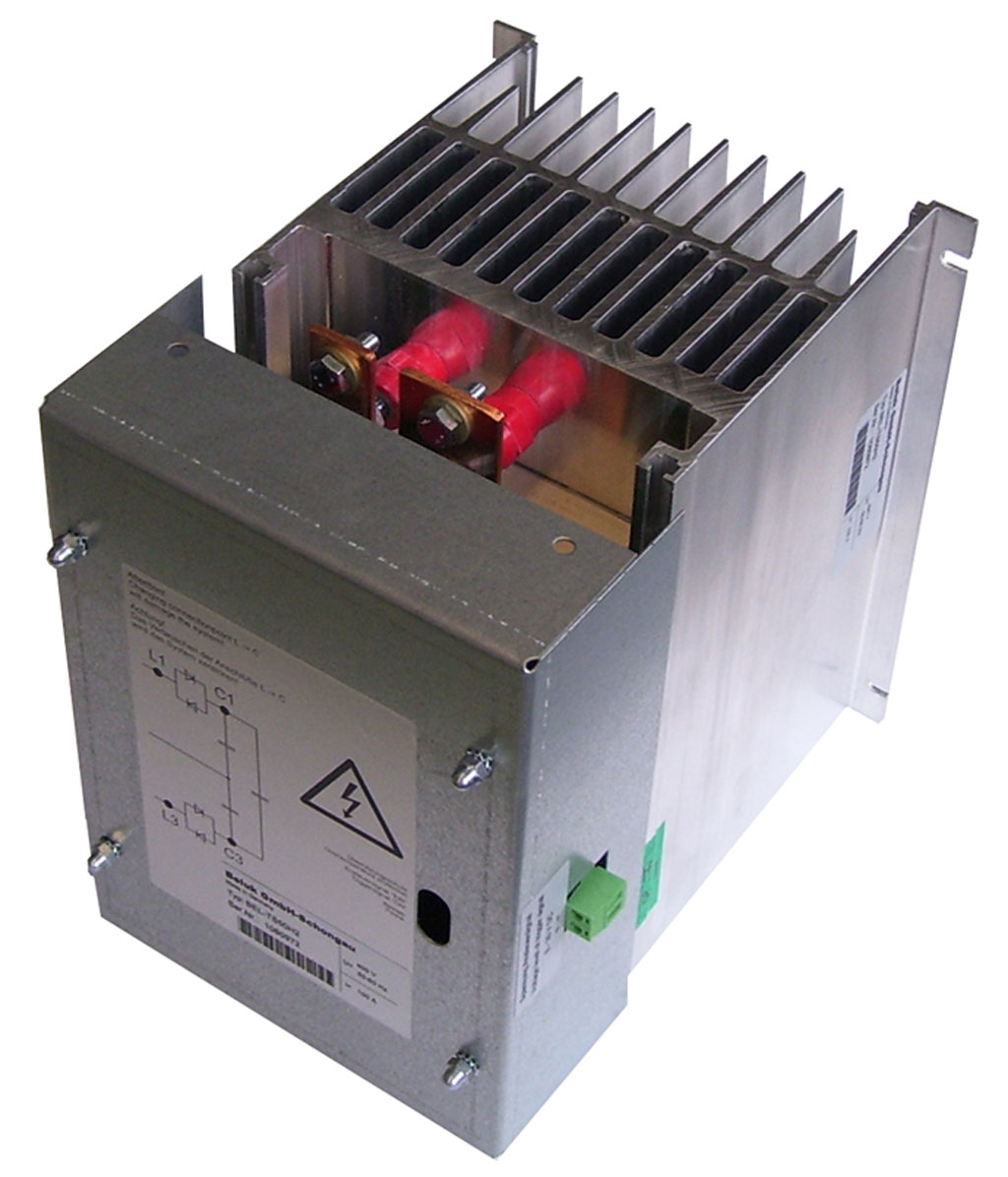
Thyristor Contactor for rapid switching of Capacitors in Low Voltage Grids
Dynamic compensation
Fast switching of capacitors with thyristor contactor
Power grids are connected not only motor´s and other electricity consumers
the continuously over a long period of time have the same electrical power.
In many industrial company and office buildings equipment and systems are installed, which have large changes of in performance at very short intervals.
Typically these are:
- Welders
- Electric resistance welding
- Crane systems
- Presses and punches
- Squaring shear
- Elevator
- Electromagnets
- Data centers
- Wind turbines
Arise in many of these plants, due to the rapid change of the load, power supply problems.
A conventional reactive power compensation system switches with contactors turn on
and off .
Because these at an arbitrary time three-phase switches to, are must be the capacitors discharged before, since otherwise a short circuit is switched.
The discharge time is usually longer than a half minute.
At this time, can be compensated but thus no short peaks.
This can cause that a large number of fast switching electrical consumers a with contactors power compensation system never switch.
Remedy the dynamic reactive power compensation.
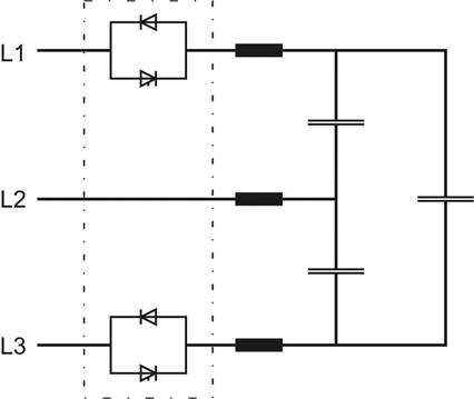
These three phases are not together, but switched with thyristor in the zero crossing of each phase.
It is therefore possible in very short times (in milliseconds) wear-free supply and switch on and off.
The major advantages are clear:
| ->very short regulate time | -->Real time |
| ->the current zero crossing switching | -->no interference (Transient) by operation |
| ->operation of frequency converters |
-->no interference from the automatic power factor correction unit |
| ->continuous desired cos | -->optimum power grid relief |
| ->eliminate Power-line flicker | -->Reduces voltage dip |
| ->Wear and maintenance | -->o wear and of less maintenance |
Standard types technical Data
Typ |
FE-TS15H2 |
FE-TS25H2 |
FE-TS50H2 |
||||||
Mains voltage / V (+/- 10%) |
400 |
440 |
480 |
400 |
440 |
480 |
400 |
440 |
480 |
Nominal current / A |
22 |
20 |
18 |
36 |
33 |
30 |
72 |
66 |
60 |
Max. continuous current A |
26 |
26 |
26 |
50 |
50 |
50 |
100 |
100 |
100 |
i2t (Tvj=125°C, 8,3…10ms) / A2s |
1150 |
1150 |
8000 |
3600 |
3600 |
8000 |
15000 |
15000 |
10500 |
VRRM, VDRM / V |
1800 |
1800 |
2200 |
1800 |
1800 |
2200 |
1800 |
1800 |
2200 |
Discharge capacitors |
Attention: It’s not allowed to use discharge reactors. |
||||||||
Recovery time |
Typically 1 period |
||||||||
Switched phases |
2, half controlled |
||||||||
Supply voltage |
From power circuit (optional: separate supply) |
||||||||
Power consumption supply |
max. 9VA |
||||||||
Voltage trigger signal |
8 - 30V DC |
||||||||
Consumption trigger signal |
2mA at 12V DC |
||||||||
Over temperature protection |
N / A |
integrated in firing unit |
|||||||
Dimensions w x d x h / mm |
appr. 185 x 202 x 188 |
appr. 200 x 160 x 215 |
|||||||
Weight |
2,9 |
4,3 |
|||||||
Power losses at nominal current / W |
41 |
37 |
33 |
68 |
61 |
52 |
122 |
111 |
104 |
Cooling |
AN, air natural |
||||||||
Protection class |
IP 20 |
IP10 |
|||||||
Humidity |
10% - 95% (without moisture condensation) |
||||||||
Max. altitude |
1000m above sea level |
||||||||
Max. ambient temperature |
+45°C (operation with nominal power) |
||||||||
Min. ambient temperature |
-10°C |
||||||||
Other types available: up to 690 V (depending on the type)
up to 130 kVar (depending on the type)
Caution:
- Never use the discharge reactors.
- The discharge resistors must be adjusted performance power- and proof voltage.